Many microcontroller projects can benefit from a simple text display and small displays are widely and cheaply available. However, the cheap parallel input ones are among the more annoying devices to actually get working. There are more expensive serial ones that you just connect to a serial port and talk to with printf as usual. We are going to look at the tricky ones. The complete manual for a typical parallel-input LCD is about 40 pages long and not a tribute to the English skills of engineers. Let’s see if we can shed some light on the problem.
This is not quite as simple as it sounds. It turns out that there are two completely different kinds of message that you may want to send to a display. The obvious ones are messages that you want to appear on the screen, “Hello World!” for example. Much less obvious are messages that affect the working of the display but do not put new characters on the screen. The manufacturer calls the first kind of message data and the second kind commands. Commands allow us to alter the behavior of the display. There are commands to turn the display on and off, to scroll left and right, and a range of other effects. Data simply appear on the screen.
Simple devices like an LED or DAC simply respond directly to the individual bits. Each bit is independent of the others and any combination of bits is valid. The LCD is very different. Some combinations of bits are meaningful and some aren’t. We need to be able to the tell the device when the complete set of bits is ready. We do this by adding extra communication lines called handshaking lines that control the data transfer. They act like the handshake in an old-fashioned business deal. They signal when the deal is done.
These LCDs come in a wide variety of shapes and sizes, from 16-character wide 1-line tall devices to 40 character wide by 2-line and 20-character 4-line tall monsters. Despite these differences they all share the same controller and so we interface to them all the same way. All these LCDs come with 14-pin interfaces but you can get away with using only 10 of the wires if you want. That saves wires but adds a layer of complexity that is not usually worth it. I will describe only the full 14-wire interface.
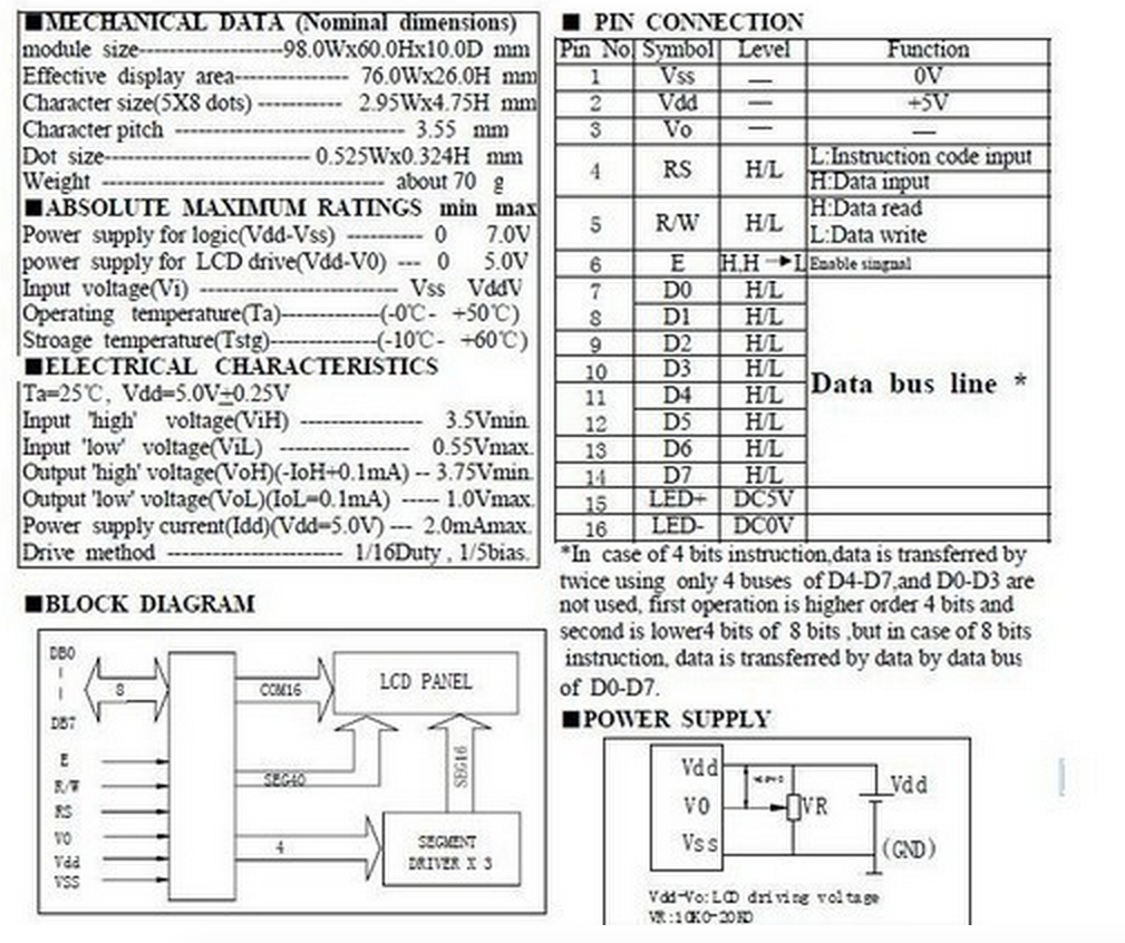
Here is what the data sheet says about the interface.
Pins 1–3 are power supply pins (we’ll more about pin 3 later). Then there are three handshaking signals, RS, R/W, and E, and finally there are the 8 data lines.
The data lines are the easiest to understand. They will take different values to send the different character codes and command codes to the LCD. The other three signals control the interaction. They are all part of the handshaking.
This is the pin that tells the LCD whether we are sending a command or sending data.
It is basically a ninth input pin that the LCD uses to decide what to do with the
8-bits coming in the data port. We need to make sure that we set the bit to HIGH if we
are sending character data and set it to LOW if we are sending a command.
The R/W wire is labeled “H:Data Read, L:Data Write”. That is correct. We can not only
send data to the LCD. We can, if we need to, read data back from the LCD. If we
decide to do that then we will have to switch the LCDPort from OUTPUT to INPUT
and back again inside our program. That is a new trick.
In practice it is perfectly possible to operate the device without ever using the read mode and we can do almost anything we want if we simply set this line to LOW and leave it that way.
The main reason to read from the display is to ask it if it ready to accept a new command or data character. Any time we send a command or data byte to the device it takes some time for LCD to process it. The LCD will completely ignore any communication that comes while it is busy. The data sheet gives a maximum time that each operation can take and will operate perfectly if we always wait that amount of time after sending each command.
However, not every action takes the full time. Sometimes the LCD finishes and is ready for new input well before the time runs out. In that case we could send data faster if we didn’t have to wait the full time. So, if you want to be absolutely safe and to get the maximum speed from the display then you need to use the read mode as well as the write mode. I won’t cover that in this introduction.
We will need to use about 1.5 data ports to drive the LCD including one complete 8-bit port (unless we want to make our lives difficult). On the TM4C123G that means that we can use port B or port D for the data and can use any other three data lines for the handshaking signals. We can use some variables to make our code insensitive to our choices of pins by doing something like this:
int LCDPort = PORTB
int RSPin = PD_0
int RWPin = PD_1
int EPin = PD_3
This serves two benefits. First it means that if we want to alter how we wire up the LCD then we only have to make changes in one place in the code. Second it makes the code more readable by giving us names that tell us about the function of the signal instead of its place on the chip.
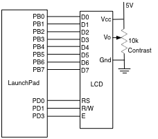
LCD pin 3 is labelled Vo without any value given. According to a figure a couple of pages later this is intended to be wired to a variable resistor set up as an adjustable voltage divider set to apply any value between 0V and 5V. This voltage sets the contrast on the LCD. It usually wants to be quite close to 0V so you can sometimes get away with simply grounding the pin. It is better, however, to wire it up as they want. Here is the complete wiring diagram.
Somewhat deeper into the documentation we find the most important picture in the whole manual. Unfortunately, it is rather complicated. Here it is.
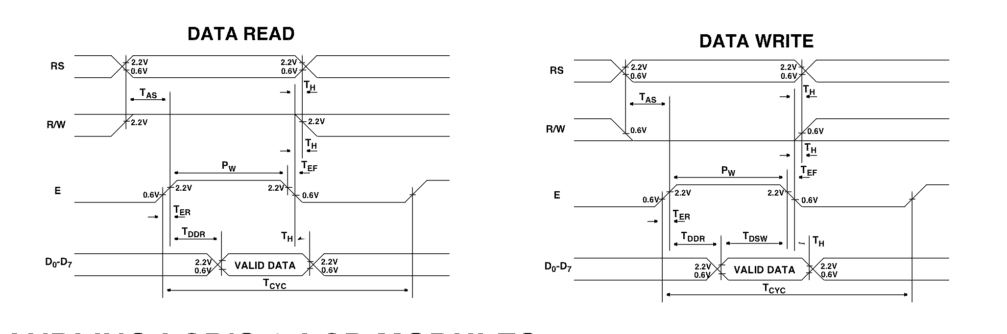
This extremely detailed picture contains far more information than we need. The first thing is to remove all the timing information. All of the vertical lines and the horizontal arrows are there to define the exact meaning of all the times with names like tAS and tDDR. We can ignore those for the moment. I have redrawn the figure without the timing and, since we are only concerned with sending data to the LCD, split out the Write Data portion.
Here is the portion of the diagram that explains how to send a single byte of data from our computer to the LCD
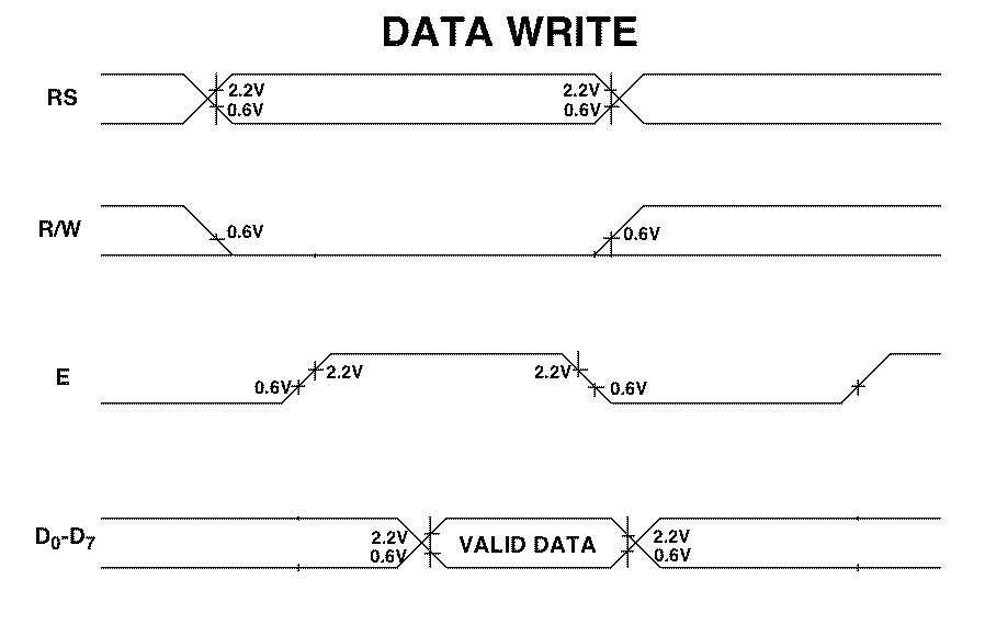
This is basically a drawing of what you should see on the screen of an oscilloscope during a data write. There is a line for each of the signals of interest except that all 8 data lines are bundled together in the bottom row.
There are several places where the diagram appears to show a signal in two states at once. For example the first sections of RS and R/W and all of the data portion. This is a conventional way to show that the state of the signal here is undetermined. It could be 0 or 1 and it does not matter to the point that the diagram is trying to make. In the case of the RS and R/W signals it means that before the transaction starts you don’t care what state those lines are in. In the case of the data and of rest of the RS signal it means that the signal needs to be in some fixed state (there are none of the cross-over things) but the details of the state can vary from data write to data write.
Now we can translate the picture. The leftmost event in the picture is the point at which RS and R/W assume their desired states. Since we are writing to the LCD R/W must go low. The state of RS will depend on whether we are sending a command (RS = 0) or some data (RS = 1). In either case, these must be done while the E line is LOW. Moreover, if we look back at the diagram with the timing info, E must stay low for at least tAS = 40nS after this change. During this time the data lines are completely ignored.
The next event is that the E line must be brought HIGH. Again, this can’t happen too soon after we set RS and R/W and it must be done at least tDDR = 360nS before the data take on their new value.
The third event is the one that we have been waiting for. We finally send the actual data byte to the data lines. We see that because the data lines show a change (the crossover) and then the next region is labelled “valid data”.
The LCD actual reads the data on the falling edge of the E signal and after that you can do what you like. The RS, R/W, and data lines are all free to change to other values. The only thing that you can’t do is bring E high again too soon. There must be at least tCYC = 500nS between writes to the device.
So every time we want to send any information to the LDC we have to go through the following complete sequence
How to send info to the LCD
    1) With E = 0 send the values of RS and RW.
    2) Bring E high.
    3) Send the data to the data port
    4) Bring E low.
This is a natural thing to encapsulate in a subroutine. In practice, I usually choose to write two different subroutines, one to send a command and one to send a data byte. They look something like
LCDWriteCommand(char cmd) {
    RS = 0
    R/W = 0
    E = 1
    LCDPort = cmd
    E = 0
}
and
LCDWriteData(char cmd) {
    RS = 1
    R/W = 0
    E = 1
    LCDPort = cmd
    E = 0
}
So we have been able to translate the diagram into two pieces of code that will form the heart of our LCD interface software.
Remember Every command or data byte that is sent to the LCD must be sent using one of these subroutines.
When the LCD receives a command or data byte from the outside world it takes it some time to process. The amount of time depends on the details of the operation. For example it takes longer to clear the entire display than to display one character. Fortunately, most commands take no more than 37μs so that if we put a short wait into the WriteCommand and WriteData routines then we are almost always safe. We just have to remember that if we call one of the long ones then we have to add an extra wait.
This simple method is quite adequate for most uses. However, it is not as fast as possible. If we want the maximum speed then we have to use the Busy flag that the LCD uses to say that it is still processing a command. This means that we will need to use the data port in bidirectional mode. That is, it will usually be an output port but for a short time at the beginning of each Write call we will turn it into an input.
Why the beginning? If we make the test at the end of the routine then we always wait the full time for the command to execute. If we put the test at the beginning then we never wait longer and sometimes wait less. We can use the time between LCD commands to do other work without worrying how long it will take. The test at the beginning of each Write routine will ensure that we don’t try to talk to the LCD until it is ready.
Any time that we play with the input/output state of a port during the life of a program we need to think carefully about the default state of the port; do we usually make it an input with occasional forays to an output or do we do it the other way. In general it is better to make input the default state because it is perfectly fine to have two inputs connected together but it is dangerous to connect two outputs.
A look at the documentation will show us that reading from the LCD is exactly as complicated as writing to it. We have to go through the same sort of handshaking scheme as writing. Here is the TestBusy routine written assuming that the LCDPort is normally left as an input port.
char LCDTestBusy() {        // returns 0 when LCD is not busy
    RS = 0      // Command read to check busy
    R/W = 1     // Makes it read instead of write
    E = 1           // Have to strobe E as before
    read LCDPort
    E = 0
    if bit 7 of LCDPort was high return 1 else return 0
}
Now that we have a way to test the busy flag we can write our safe routines. Again, remember that we normally leave LCDPort as an input.
LCDWriteCommandSafe(char cmd) {
  while (LCDTestBusy() == 1); // Wait for Busy to go low
  Make LCDPort output
    RS = 0
    R/W = 0
    E = 1
    LCDPort = cmd
    E = 0
  Make LCDPort input
}
and
LCDWriteDataSafe(char cmd) {
  while (LCDTestBusy() == 1); // Wait for Busy to go low
  Make LCDPort output
    RS = 1
    R/W = 0
    E = 1
    LCDPort = cmd
    E = 0
  Make LCDPort input
}
In an ideal world, an LCD would initialize itself into a sensible state when the power was first applied. In practice, these small LCDs ado not do so reliably and we must go through a special startup sequence. Here is the sequence as given in the manual.
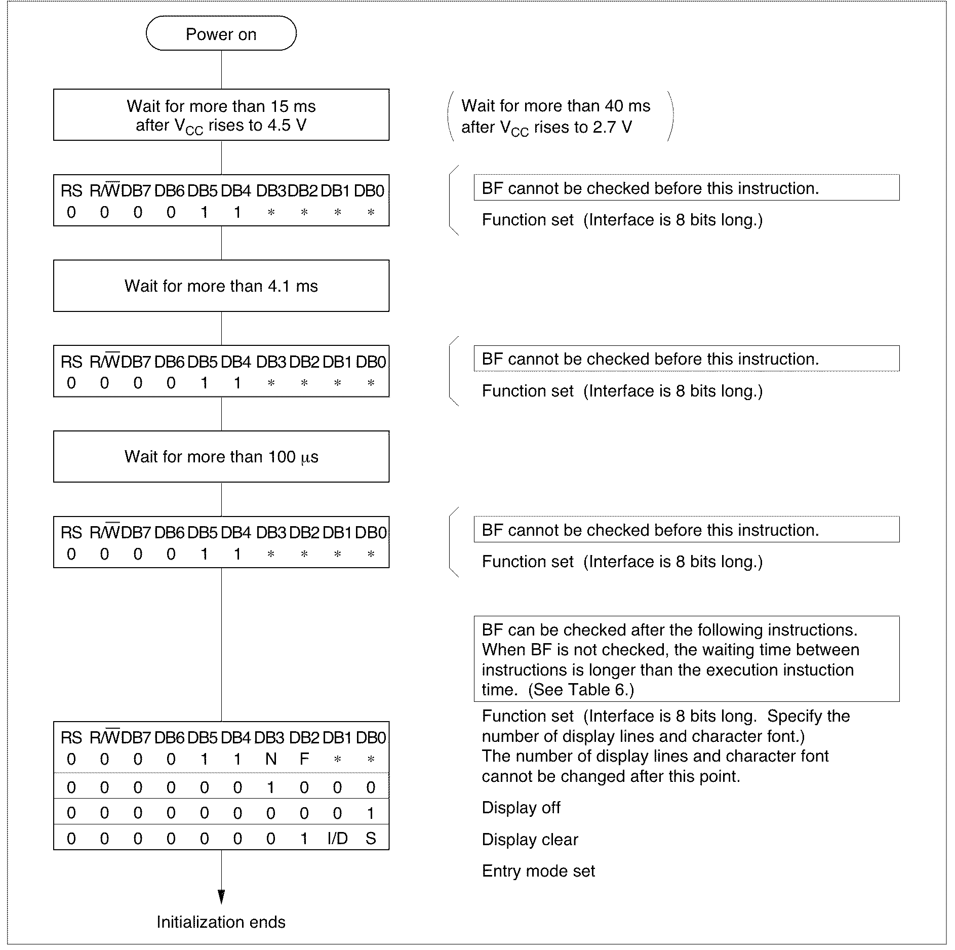
This does not look too bad. We need to send the LCD a command with value 0x30 (well, the first hex digit must be 3, the second is a don’t care). We have to send it three times with some careful waits between. I usually assume that the LCD gets power at the same time that the computer does so I assume that I need to include the first 15mS wait.
Note that we are not allowed to test the Busy flag during this process so we need to use the plain LCDWriteCommand. Thus the sequence begins
Wait 15mS
LCDWriteCommand(0x30)
Wait 4.1mS
LCDWriteCommand(0x30)
Wait 0.1mS
LCDWriteCommand(0x30)
After this we can check the busy flag or we can use the default wait.
Two things remain to be decided. We have to tell the controller about the display that it is driving, we have to select the input mode, and we will need to turn the display back on.
At this point, the LCD driver chip is in 8-bit mode but it does not know what kind of display it is talking to. We must tell it how many (logical) lines there are and choose one of two possible fonts for it to display.
These chips can drive displays with enough pixels for either 1 line of text or 2. Most small displays only support one line and so usually I set the N bit to 0.
There is also a choice of font. I have not seen a single-line display that does not have enough pixels to support the more readable 5x10 dot font so I usually set the F bit to 1.
Together these make up the next command. The template in the initialization sequence figure tells us to use the format 0b0011NF– so that we can use 0b00110100 = 0x38 for the next command.
The next two are very straightforward since they are prescribed completely. That leaves us with the entry mode.
This is one of fiddlier ones to get right. The display is capable of operating in several modes. The obvious one simply writes characters from left to right, starting at the leftmost. However you can also scroll characters in from left or right and an unfortunate mix of entry mode and starting point can make the display show no characters at all. I have found the most useful starting mode is I/D=1, S=0, which produces the desired left-right screen-like behaviour.
The last thing that we must do is turn the display on. According to the manual this uses a command of the form 0b00001DCB, where the lowest three bits mean
*D 1 turns display on, 0 turns it off *C 1 turns the cursor on, 0 turns it off *B 1 makes the cursor blink, 0 turns it off
I usually just turn the whole thing on.
Noting that none of these commands takes more than 37uS to have effect we end up with the complete initialization sequence.
Wait 15mS
LCDWriteCommand(0x30)
Wait 4.1mS
LCDWriteCommand(0x30)
Wait 0.1mS
LCDWriteCommand(0x30)
Wait 0.1mS
LCDWriteCommand(0x38)   // Set num lines and font
Wait 0.1mS
LCDWriteCommand(0x08)   // Display off
Wait 0.1mS
LCDWriteCommand(0x01)   // Clear Display
Wait 0.1mS
LCDWriteCommand(0x06)   // Set entry mode
Wait 0.1mS
LCDWriteCommand(0x0F)   // Display on, cursor on, blink
Wait 0.1mS
NOTE It is perfectly possible to use the busy-checked command write starting from the 0x38 command but it is easier to get the system working for the first time if you use the simple wait method. Once your LCED is operating properly you can always switch to the more efficient form.
The controller chip in these LCDs already understands the ascii code. This means that it is really easy to write text. For example, to display the letter ‘a’ at the current position we simply call
LCDWriteData('a')
or its safe version. Each letter will appear to the right of the previous letter until you run out of space on the display, when the letters will be lost into the void. This limits us to short messages.
Note that the controller does NOT support ascii control sequences. If you send it a carriage return (0x0D) then it will not affect the cursor position but will instead cause some random character pattern to appear. You can get the effect of a carriage return/linefeed sequence by calling the clear command
LCDWriteCommand(0x01) // Clear Display
In addition to clearing the screen and resetting the cursor to the beginning of the line you can move the cursor to an arbitrary position with the “Set DDRAM address” command
0b1aaaaaaa
where the a’s are a 7-bit address Since the chip only has a total of 80 data memory locations the value of aaaaaaa should be between 0 and 79 (0x4F). On a typical 16-character display you will want to keep the address between 0 and 0x0F.
With this command you can set the location at which the next character will appear. For example, you could write a voltage so it looked like this
V= 14.5V
and then set the cursor position (data address) to 2 and write a new number, say 21.3, and the display would then read
V= 21.3V
where the V= and V were left from the previous time and the ’ 21.3’ was new text.