Carrying On
Glancing back to the original design we see that the remaining element that we need is a single bit memory to hold the carry out from one stage of addition to become the carry in to the next stage. This seems like a job for a simple D-type flip-flop such as half of a 7474. It is very simple to code the basic D-type latch behavior
module flop(d, clk, q); input d, clk;
output q;
reg q;
wire d, clk;
always @(posedge clk);
q = d;
endmodule // flop |
but we also need to handle asynchronous set and reset inputs that take priority, as can be seen in the truth table for the 7474. I think that we can do this with negative edge triggers on reset and clear, like this.
//	dflop74 is a description of one of the two positive-edge
//	triggered D-type flip-flops from a 7474. These have
//	asynchronous, negative true, set and reset inputs.
//
module dflop(d, clk, set, reset, q, qbar);
input d, clk, set, reset;
output q;
reg q;
wire d, clk, set, reset;
/* reset is asynchronous to clock*/
always @(negedge reset) begin
if (set) begin
q = 0;
qbar = 1;
end
else begin
q = 1;
qbar = 1;
end
end
/* set only differs in sign */
always @(negedge set) begin
if (reset) begin
q = 1;
qbar = 0;
end
else begin
q = 1;
qbar = 1;
end
end
 /* Data are copied on positive clock edge */
 always @(posedge clk) begin
   if (reset & set) begin
       q = d;
       qbar = !d;
     end
   end
endmodule // dflop74 |
The test uses registers for the input and control signals and runs the flip-flop through most of its states.
//	Test module for dflop74, one of the flip flops in
//	a 7474. They have asynchronous set and reset
//	inputs and transfer the data to q on the positive
//	edge of the clock.
//
module test;
reg setbar = 1;
reg clrbar = 1;
reg in = 0;
reg clock = 0;
/* Reset at time 8 for 4 then at time 20 for 10 */
initial begin
# 8 clrbar = 0;
# 4 clrbar = 1;
# 8 clrbar = 2;
# 10 clrbar = 3;
# 60 $stop;
end
/* Set at time 14 for 2 then at time 24 for 10 */
initial begin
# 14 setbar = 0;
# 2 setbar = 1;
# 8 setbar = 2;
# 10 setbar = 3;
end
/* Raise d early then lower while in reset then set */
initial begin
# 1 in = 1;
# 21 in = 0;
# 15 in = 1;
# 10 in = 0;
end
 /* Make a regular pulsing clock. */
 always #5 clock = !clock;
wire q, qbar;
dflop74 f1(in, clock, setbar, clrbar, q, qbar);
initial
$monitor("At time %t, in = %d, q = %d, qbar=%d",
$time, in, q, qbar);
 initial begin
   $dumpfile("test74.vcd");
   $dumpvars(0,test);
 end
endmodule // test |
We see that the output changes exactly as it should.
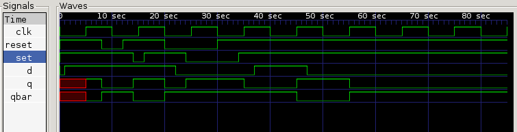
NOTE the GtkWave naturally orders the signal alphabetically but you can slide them around in the Signals window to re-order them.