Interfacing Text LCDs
Many microcontroller projects can benefit from a simple text display and small displays are widely and cheaply available. However, the cheap parallel input ones are among the more annoying devices to actually get working. There are more expensive serial ones that you just connect to a serial port and talk to with printf as usual. We are going to look at the tricky ones. The complete manual for a typical parallel-input LCD is about 40 pages long and not a tribute to the English skills of engineers. Let's see if we can shed some light on the problem.
Talking to a Display
This is not quite as simple as it sounds. It turns out that there are two completely different kinds of message that you may want to send to a display. The obvious ones are messages that you want to appear on the screen, "Hello World!" for example. Much less obvious are messages that affect the working of the display but do not put new characters on the screen. The manufacturer calls the first kind of message data and the second kind commands. Commands allow us to alter the behavior of the display. There are commands to turn the display on and off, to scroll left and right, and a range of other effects. Data simply appear on the screen.
Simple devices like an LED or DAC simply respond directly to the individual bits. Each bit is independent of the others and any combination of bits is valid. The LCD is very different. Some combinations of bits are meaningful and some aren't. We need to be able to the tell the device when the complete set of bits is ready. We do this by adding extra communication lines called handshaking lines that control the data transfer. They act like the handshake in an old-fashioned business deal. They signal when the deal is done.
Down to the Wires
These LCDs come in a wide variety of shapes and sizes, from 16-character wide 1-line tall devices to 40 character wide by 2-line and 20-character 4-line tall monsters. Despite these differences they all share the same controller and so we interface to them all the same way. All these LCDs come with 14-pin interfaces but you can get away with using only 10 of the wires if you want. That saves wires but adds a layer of complexity that is not usually worth it. I will describe only the full 14-wire interface.
Here is what the data sheet says about the interface.
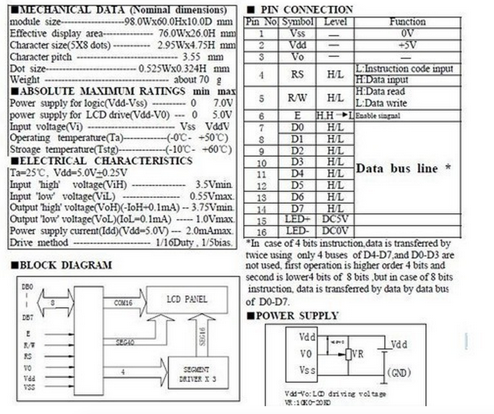
Pins 1-3 are power supply pins (we'll more about pin 3 later). Then there are three handshaking signals, RS, R/W, and E, and finally there are the 8 data lines.
The data lines are the easiest to understand. They will take different values to send the different character codes and command codes to the LCD. The other three signals control the interaction. They are all part of the handshaking.
RS
This is the pin that tells the LCD whether we are sending a command or sending data.
It is basically a ninth input pin that the LCD uses to decide what to do with the
8-bits coming in the data port. We need to make sure that we set the bit to HIGH if we
are sending character data and set it to LOW if we are sending a command.
R/W
The R/W wire is labeled "H:Data Read, L:Data Write". That is correct. We can not only
send data to the LCD. We can, if we need to, read data back from the LCD. If we
decide to do that then we will have to switch the LCDPort from OUTPUT to INPUT
and back again inside our program. That is a new trick.
In practice it is perfectly possible to operate the device without ever using the read mode and we can do almost anything we want if we simply set this line to LOW and leave it that way.
Why Read a Display?
The main reason to read from the display is to ask it if it ready to accept a new command or data character. Any time we send a command or data byte to the device it takes some time for LCD to process it. The LCD will completely ignore any communication that comes while it is busy. The data sheet gives a maximum time that each operation can take and will operate perfectly if we always wait that amount of time after sending each command.
However, not every action takes the full time. Sometimes the LCD finishes and is ready for new input well before the time runs out. In that case we could send data faster if we didn't have to wait the full time. So, if you want to be absolutely safe and to get the maximum speed from the display then you need to use the read mode as well as the write mode. I won't cover that in this introduction.
Wiring the Wires
We will need to use about 1.5 data ports to drive the LCD including one complete 8-bit
port (unless we want to make our lives difficult). On the 9S08GT16 that means that
we can use port A or port B for the data and can use any other three data lines
for the handshaking signals. We can use the #define trick to make our code insensitive
to our choices of pins by doing something like this:
#define LCDPort PORTA
#define RSPin PTD0
#define RWPin PTD1
#define EPin PTD3
This serves two benefits. First it means that if we want to alter how we wire up the LCD then we only have to make changes in one place in the code. Second it makes the code more readable by giving us names that tell us about the function of the signal instead of its place on the chip.
Shaking Hands
Somewhat deeper into the documentation we find the most important picture in the whole manual. Unfortunately, it is rather complicated. Here it is.
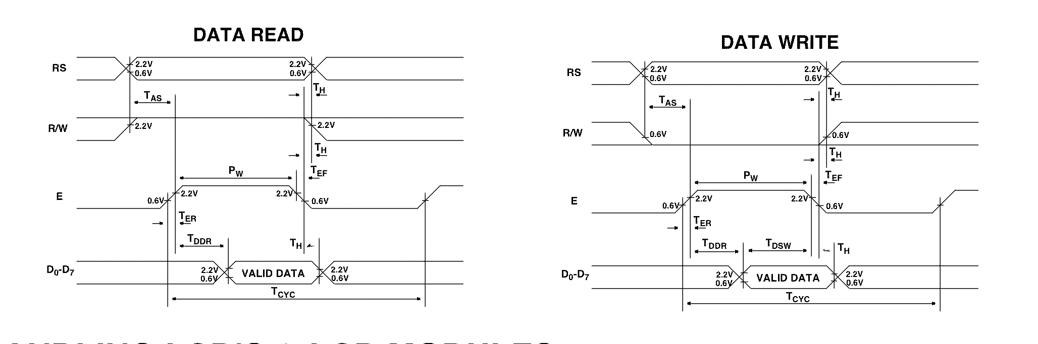
This extremely detailed picture contains far more information than we need. The first thing is to remove all the timing information. All of the vertical lines and the horizontal arrows are there to define the exact meaning of all the times with names like tAS and tDDR. We can ignore those for the moment. I have redrawn the figure without the timing and, since we are only concerned with sending data to the LCD, split out the Write Data portion.
Sending Data to the LCD
Here is the portion of the diagram that explains how to send a single byte of data from our computer to the LCD
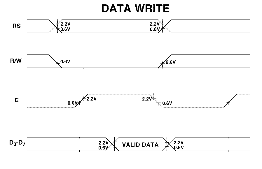
This is basically a drawing of what you should see on the screen of an oscilloscope during a data write. There is a line for each of the signals of interest except that all 8 data lines are bundled together in the bottom row.
There are several places where the diagram appears to show a signal in two states at once. For example the first sections of RS and R/W and all of the data portion. This is a conventional way to show that the state of the signal here is undetermined. It could be 0 or 1 and it does not matter to the point that the diagram is trying to make. In the case of the RS and R/W signals it means that before the transaction starts you don't care what state those lines are in. In the case of the data and of rest of the RS signal it means that the signal needs to be in some fixed state (there are none of the cross-over things) but the details of the state can vary from data write to data write.
Now we can translate the picture. The leftmost event in the picture is the point at which RS and R/W assume their desired states. Since we are writing to the LCD R/W must go low. The state of RS will depend on whether we are sending a command (RS = 0) or some data (RS = 1). In either case, these must be done while the E line is LOW. Moreover, if we look back at the diagram with the timing info, E must stay low for at least tAS = 40nS after this change. During this time the data lines are completely ignored.
The next event is that the E line must be brought HIGH. Again, this can't happen too soon after we set RS and R/W and it must be done at least tDDR = 360nS before the data take on their new value.
The third event is the one that we have been waiting for. We finally send the actual data byte to the data lines. We see that because the data lines show a change (the crossover) and then the next region is labelled "valid data".
The LCD actual reads the data on the falling edge of the E signal and after that you can do what you like. The RS, R/W, and data lines are all free to change to other values. The only thing that you can't do is bring E high again too soon. There must be at least tCYC = 500nS between writes to the device.
So every time we want to send any information to the LDC we have to go through the following complete sequence
How to send info to the LCD
    1) With E = 0 send the values of RS and RW.
    2) Bring E high.
    3) Send the data to the data port
    4) Bring E low.
This is a natural thing to encapsulate in a subroutine. In practice, I usually choose to write two different subroutines, one to send a command and one to send a data byte. They look something like
LCDWriteCommand(char cmd) {
    RS = 0
    R/W = 0
    E = 1
    LCDPort = cmd
    E = 0
}
and
LCDWriteData(char cmd) {
    RS = 1
    R/W = 0
    E = 1
    LCDPort = cmd
    E = 0
}
So we have been able to translate the diagram into two pieces of code that will form the heart of our LCD interface software.
Remember Every command or data byte that is sent to the LCD must be sent using one of these subroutines.