Testing the Adder
We have built the strucutre of the adder but in oreder for it actually to add two numbers we have to provide a lot of control signals in a very special pattern. Here is my first attempt at an outline of the control process.
1) Reset all the registers and flip-flops.
2) Load the input data into the registers.
3) Shift 8 bits to the right through the adder.
Rewriting this in terms of the control signals I get
1) Defailt state of inputs is mode=0, reset=1, clk running.
2) reset=0 for a short time then reset=1 (reset all registers and flip-flops).
2) Before a rising clk set inA and inB, mode=3, after clk mode=0 (load registers).
3) Before rising clk set mode=2 and hold for 8 clocks then mode = 0 (shift 8-bits right).
With that I can write a test program.
//
//	Test for serial adder sadd2.
//	Adder is defined as
//		module sadd(inA, inB, modeA, modeB, clk, rst);
//
//	inA and inB are parallel loaded 8-bit input values
//	modeA and modeB are 2-bit inputs to
module test;
/* Make reg inputs */ /* We need input bus values and clock, mode, and reset as inputs */ reg [7:0] inbus1 = 0; reg [7:0] inbus2 = 0; reg [1:0] mode = 0; // 0 is hold reg clk = 0; reg reset = 1; // Reset for sadd is active low /* Make a regular pulsing clock. */ always #5 clk = !clk; /* Then a list of timed events */
initial begin
# 1 reset = 0; /* Reset all regs */
# 5 reset = 1; /* Comes out of reset at time 6 */
# 1 inbus1 = 63;
# 0 inbus2 = 59;
# 1 mode = 3; /* Switch to load mode at time 8 */
# 10 mode = 2; /* Switch to shift at 18 */
# 80 mode = 0; /* Back to hold after 8 clock periods */
# 2 $finish;
end
sadd a1(inbus1, inbus2, mode, mode, clk, reset);
initial
$monitor("At time %d, mode = %h", $time, mode);
initial begin
$dumpfile("saddtest.vcd");
$dumpvars(0,test);
end
endmodule // test |
I couldn't put in anything to monitor the output because there isn't any! But in GtkWave I can look at all the signals so here is my GtkWave screen. Note that I have had to add signals from more than one level of the system.
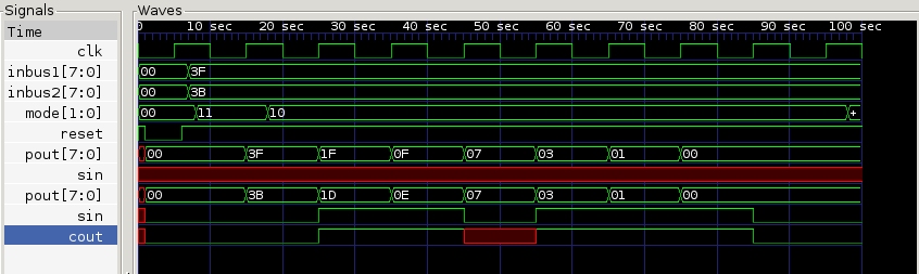
The main thing that we see is that it does not work. We do NOT end up with the answer in register A (the first of the pout[7:0] entires) nor with the addend in register B (the second). At least part of the problem appears when we look at the serial input to register A (the line labeled sin) which never takes a defined state. Looking at the signals in the adder I find that carry in never becomes defined. Looking at the signals in the flip-flop I learn that set and reset don't seem to have real values and so the latch never enters a valid state.