A Working Adder
Here is the latest version of the testbench, using two different mode sets so that the registers can shift different numbers of bits.
//
//	Test for serial adder sadd2.
//	Adder is defined as
//		module sadd(inA, inB, modeA, modeB, clk, rst);
//
//	inA and inB are parallel loaded 8-bit input values
//	modeA and modeB are 2-bit inputs to
module test;
/* Make reg inputs */ /* We need input bus values and clock, mode, and reset as inputs */ reg [7:0] inbus1 = 0; reg [7:0] inbus2 = 0; reg [1:0] mode1 = 0; // 0 is hold reg [1:0] mode2 = 0; // 0 is hold reg clk = 0; reg reset = 1; // Reset for sadd is active low /* Make a regular pulsing clock. */ always #5 clk = !clk; /* Then a list of timed events */
initial begin
# 1 reset = 0; /* Reset all regs */
# 5 reset = 1; /* Comes out of reset at time 6 */
# 1 inbus1 = 63; /* Values to add */
# 0 inbus2 = 59;
# 1 mode1 = 3; /* Switch to load mode at time 8 */
# 0 mode2 = 3;
# 10 mode1 = 2; /* Switch to shift at 18 */
# 0 mode2 = 2;
# 80 mode2 = 0; /* RB to hold after 8 clock periods */
# 10 mode1 = 0; /* RA takes one more clock */
# 2 $finish;
end
sadd a1(inbus1, inbus2, mode1, mode2, clk, reset);
initial
$monitor("At time %d, mode = %h", $time, mode1);
initial begin
$dumpfile("saddtest.vcd");
$dumpvars(0,test);
end
endmodule // test |
The following output from GtkWave shows that this system works nicely!
This time we end with register A (the first pout) holding the correct value (0x3f+0x3B=0x7A) and register B stopping atits correct value of 0x3B.
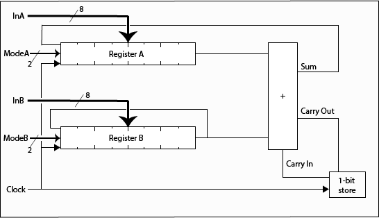
So why does it take one more clock pulse for register A than register B? Well, looking again at the overall diagram

we see that the feedback for register goes through the adder while that for register B is connected straight back to its input. On the first clock pulse of the shift the input to register B is already correct while that for register A has to wait for the summation process (maybe?).

